

Welcome
Dr. James F. Roberts is an Australian entrepreneur and flying robot specialist with almost two decades of experience in Unmanned Aerial Vehicles (UAVs)/Drones. This site shows some of his work mainly from his PhD. studies completed in Lausanne Switzerland.
While working in two challenging and inspiring Start-up companies abroad, James has been bridging the gap between research and product commercialization.
He believes that Australia should invest in local innovation and technology-based Start-ups. For this reason, he turned down other opportunities to come home with his family and start his own company in NSW Australia. He is now working on the next generation of locally-made drones to deliver to Australia and the world.

Bio
For almost two decades, Dr. James F. Roberts has been gaining professional research and commercialization experience, spanning multi-disciplinary fields including aeronautics, microelectronics, control systems, mechanics, and product development.
In 2004, James received a Bachelor of Engineering in Microelectronics Engineering, majoring in communications systems, from Griffith University, Brisbane. His multi-award-winning graduation project with Airservices Australia, entitled “A Design for Air-Traffic Audio Control”, now manages 11% of the world’s airspace. As part of his Microelectronics Bachelor from Griffith University, he worked with a research team at the Intelligent Control Systems Laboratory. There, he developed a control board that was used in the “Digital Control Systems course.
In 2004, James started his first business, Jimonics Engineering Solutions, which is a contractor and consultancy business for microelectronic systems, specializing in robotics and avionics. Custom solutions have been designed for a broad range of clients including; Airservices Australia, EPFL University, The University of Sydney, and the “Musée de Zoologie de Lausanne”.
In 2007, James received a Master of Engineering in Aeronautical, Mechanical & Mechatronic Engineering at The University of Sydney. His master thesis, entitled: “Design of an Autonomous Hovering Miniature Air Vehicle as a Flying Research Platform”, aimed towards bringing UAV technology into education.
In 2011, James completed a Ph.D. at the Laboratory of Intelligent Systems, EPFL Switzerland. His doctoral thesis, entitled, “Enabling the Collective Operation of Indoor Flying Robots”, was part of the highly successful international “Swarmanoid“, Future Emerging Technologies project, funded by the European Commission.
From 2011, James was the Chief Technology Officer at Intelligenia DYNAMICS, a Spanish start-up company. There he was researching and commercializing an “Energy-aware Aerial Swarm Search UAV for Efficient Search and Rescue”. To support this research, he was awarded a Marie Curie fellowship from the European Commission, and a Torres Quevedo research grant from the Spanish Ministry of Science.
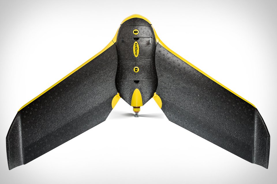
Between 2012 and 2014, James was the Lead Mechanical Engineer, at senseFly , a Swiss start-up company. There he was developing the next generation of small (<2kg) Unmanned Aerial Vehicles (UAVs) for civil professional applications. Some of his work includes the highly successful eBee fixed-wing drone for 3D mapping, and the Albris (Exom) quad-rotor, designed for remote inspection.
In 2016, James was an invited UAV specialist to a discovery workshop discussing the possibilities of using UAVs for disaster response. The workshop was organized by Instedd and was held at Singularity University within the NASA Ames Research Park in Silicon Valley.
James is now the Directing Founder of True Blue AEROO, combining the three pillars of Robotics; Electronics, Mechanics, and Software, to create unique drone and communications products for the harsh Australian environment.


Ph.D Research
What are the Eyebots and what can they do?
James developed the Eyebots while completing his doctoral thesis in the Laboratory of Intelligent Systems, EPFL Switzerland. The Eyebots are part of the highly successful international “Swarmanoid”, Future Emerging Technologies project, funded by the European Commission.
Eyebots are autonomous flying robots with powerful sensing and communication abilities for search, monitoring, and path-finding within built environments. They operate together in a swarm, to efficiently explore built environments, locate predefined targets, and guide other robots or humans.
Eyebot Feature Film
This video shows a close-up of all the cool features that were packed into the Eyebots. Including; carbon fiber structure, magnetic ceiling attachment mechanism, various control boards – with a speech synthesizer ;o), inertial sensors, HD video camera with a laser pointing device, embedded Linux computer, custom infrared based 3D relative positioning sensor ring with collision avoidance, and four powerful coaxial brush-less motors.
What is the Swarmanoid Project?
Eyebots are part of the Swarmanoid, a European research project aimed at developing a heterogeneous swarm of wheeled, climbing, and flying robots that can carry out tasks normally assigned to humanoid robots. Eyebots serve the role of the eyes within the Swarmanoid and guide other robots that have simpler sensing abilities. Eyebots can also be deployed on their own within built environments to locate humans who may need help, suspicious objects, or traces of dangerous chemicals. Their programmability, combined with swarm intelligence behaviors, makes them rapidly adaptable to several types of situations that may pose a danger to humans.

Swarmanoid, the Movie
This is a video that all the Swarmanoid partners put together. It describes the entire project and the goal of using a swarm of heterogeneous robots to search an unknown environment and collect an object of interest (in this case a book on a shelf). This task may be trivial for you and me, however, trying to do this with a robot is very difficult. It is even more complex with a swarm of robots. The idea of using a swarm of robots instead of a single humanoid robot allows for multiple robot failures before the task can no longer be achieved. Take a look at the video.
What is a 3D relative Positioning Sensor?
Relative positioning sensors constitute the holy grail of collective robotics. They allow multiple robots to cooperate and work together in a team to achieve a common goal. Relative positioning sensors use simple, local sensing and communication in the form of distances and angles between neighboring robots. This simple local sensing and communication minimizes the embedded computational requirements, as the relative position information is directly attained.
By having at least one flying robot stationary, used as a static reference point, several flying robots can use relative positioning information to achieve position control, mitigate platform drift, enable goal-directed flight and achieve collective operation. Such an approach could be used in most situations, as it does not rely on feature extraction in the surrounding environment like SLAM-based (laser scanner and vision) approaches and is computationally simple.

What is the PhD. Thesis about?
“Enabling the Collective Operation of Indoor Flying Robots”
The goal was to develop a practical methodology for enabling energy-efficient, autonomous indoor flying robots capable of inter-robot spatial coordination for unprepared indoor environments, without using external aids. In order to achieve this several practical methodologies have been proposed and demonstrated. The developed methodologies have enabled the collective operation of indoor flying robots, without using external aids.

Thesis Referenced Videos
James is one of the pioneers of autonomous quad-rotor technology. The videos below show various results from topics that are referenced within the thesis, under the corresponding chapters. The majority of this work was done back in 2006 to 2009.
Chapter 3:
Quad-rotor Autonomous Altitude
This is a video of a custom-built quad-rotor made entirely from Printed Circuit Board (FR4), with the electronics embedded directly into the frame. It uses an ultrasonic sensor to automatically take off and fly at a constant height off the ground.
Quad-rotor obstacle avoidance behavior
To track the trajectory of the robot, this low-resolution video is taken from above with a fish-eye lens and then later post-processed in MATLAB. The robot is a custom-built quad-rotor made entirely from Printed Circuit Board (FR4), with the electronics embedded directly into the frame. It uses four infrared sharp distance sensors (spaced at 90 degrees) and one ultrasonic sensor for altitude, to fly autonomously within a room, with an obstacle avoidance behavior.
Quad-rotor anti-drift behavior
This is the same setup as above but the embedded controller is coded for an anti-drift behavior.
Chapter 4:
Quad-rotor ceiling attachment
This video shows a custom-built quad-rotor that uses one ultrasonic sensor for altitude-controlled ceiling attachment. X and Y positioning is done by manual remote control. A hall-effect sensor determines when the robot is attached and powers down the rotors. The system can also detach automatically and recover to a pre-defined altitude. The system uses a magnet to attach to ferrous ceilings as a proof of concept.
Chapter 5:
Sensor calibration
This video shows how the Eyebots 3D relative positioning sensors were calibrated. There are 48 infrared receiver photo-diodes and 160 infrared emitters per sensor ring. One ring was used in transmitting mode (on the wheeled robot) and the other ring (under calibration on the ABB) was used in receiving mode.
The infrared 3D relative positioning sensor was calibrated using an ABB robotic arm and a wheeled robot, which drives along a track. High-accuracy signal strength measurements, for all 48 photodiodes (spaced in 3D around the ring), were taken at 10cm increments up until 6m. This is later used in a look-up table to estimate the range, bearing, and elevation between any two Eyebots.
Sensor characterization
This video shows how the Eyebots 3D relative positioning sensors were characterized. There are 48 infrared receiver photo-diodes and 160 infrared emitters per sensor ring. One ring was used in transmitting mode and the other ring (under test) was used in receiving mode. Three lasers were used to align the distance and the bearing and elevation angles. The transmitting sensor is continuously rotated by a motor to obtain a full intensity range infrared pattern variation within the results. The receiving ring is then moved through a 1m x 1m grid to obtain the characterization data. This is done to determine the 3D sensors’ range, bearing, and elevation performance.
Chapter 6:
Energy efficient swarm search
This is a simulation video that was coded by Dr. Timothy Stirling. It shows the basic navigation and search algorithm that is used in the Swarmanoid Scenario demonstration. The sensor network algorithm is based on systematic incremental deployment/re-deployment, and a sweep search. Blue beacons guide green-flying explorers. The hop-count gradients guide the deployment. Green hops are used in corridors and red are used in rooms. The hops safely control the detachment. Systematic, incremental deployment is energy efficient. Beacons guide robots and humans at the base to the located target.
Eye-bot hovering collision
In this demo, there are two Eyebots, one flying and one placed on the shelf at the end of the room. The flying Eye-bot controller is coded to stay at a fixed position in the middle of the room. The infrared proximity sensors are then used to prevent the Eye-bot from crashing into the walls. The proximity sensors are non-linear so it behaves a bit like an invisible cushion that pushes away from obstacles. As it is using the amplitude of the infrared reflection, the larger and more reflective the obstacle is the better it can detect it (hence the limited response from my hand).
The system relies solely on an onboard infrared 3D relative positioning sensor (the ring around the bottom) to determine its position in 3D space, with respect to other Eyebots. It is also capable of proximity sensing in order to avoid obstacles (e.g walls, people) up to a few meters away.
Eye-bot ping-pong
In this demo, there are two Eyebots, one flying and one placed on the floor at the end of the room. The flying Eye-bot controller is coded to cycle between two waypoints a few meters apart, it basically flies between the two waypoints until the batteries are flat.
The system relies solely on an onboard infrared 3D relative positioning sensor (the ring around the bottom) to determine its position in 3D space, with respect to other Eyebots. It is also capable of proximity sensing in order to avoid obstacles (e.g walls, people) up to a few meters away.
Eye-bot tracking
In this demo, there are three Eyebots, one flying, one placed on the floor at the end of the room, and one attached to the ceiling. The flying Eye-bot is commanded to fly along the chain of robots and attach to the ceiling at the end of the room. The stationary Eyebots are used as 3D reference points.
The system relies solely on an onboard infrared 3D relative positioning sensor (the ring around the bottom) to determine its position in 3D space, with respect to other Eyebots. It is also capable of proximity sensing in order to avoid obstacles (e.g walls, people) up to a few meters away.
Eye-bot scenario
In this demo, there are seven Eyebots searching a building for a desired object. The stationary Eyebots are used as 3D reference points to guide the 3D path of the Flying Eye-bot. One Eye-bot is deployed at a time to search the building. Once each Eye-bot reaches the limit of its 3D sensor range, it attaches to the ceiling. Each Eye-bot does the same to extend the search chain further into the unknown environment. The search continues until the object has been found using their onboard camera (in this case a book on the shelf). The Eyebots then communicate back down the chain to stop more Eyebots from being deployed.
The system relies solely on an onboard infrared 3D relative positioning sensor (the ring around the bottom) to determine its position in 3D space, with respect to other Eyebots. It is also capable of proximity sensing in order to avoid obstacles (e.g walls, people) up to a few meters away.
Appendix:
Distance scanner
This is an induction-based contactless distance scanner designed for a quadrotor. It uses two rotating sharp infrared sensors. Power is transferred between two coils, one secondary coil attached to the rotating part and another primary coil attached to the base. An H-bridge is used to drive the primary coil. Data is transferred through an NRF wireless transceiver. A simple PD controller is used to balance the distances in all directions to push the quadrotor away from obstacles.